Tailored
Test Solutions
test services climatic chambers environmental chambers durability testing climatic testing vibration testing data acquisition test consultancy tensile test machines Lloyd LRX Instron MTS Sanwood Salt spray chamber rain chamber tts tts tts strain gauging vibration testing shaker testing durability testing mechanical testing salt spry HAST chamber 3D printing Test 3D Print 3d PLA ABS how to test 3d printed parts mechanical testing of 3d parts additive manufacturing Lloyd EZ50 500kN WCAC Testing Water charge air testingLDS V721 shaker ozone calibration Motorsport PAS sterring rack pump testing

Tailored Test Solutions Ltd

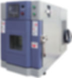
Environmental Chamber Sales
After extensive market research TTS are proud to offer the comprehensive range of Sanwood Environmental Chambers and Products to the UK market. Sanwood are one of China's biggest chamber manufacturers and are set to become a global name in this competitive market place.
-
Temperature, Temperature and Humidity, Thermal Shock, UV Ageing, Ozone, Rain Ingress, Dust Ingress, Salt Spray, Corrosion.
-
Full UK service and support from a highly skilled workforce.
-
Manufacturer backed 1 year warranty on all parts
-
Huge variety of sizes, performance and cost.
-
Trusted by some of the world's leading brands


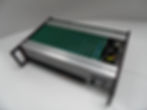
TTS 800 Amplifier Rack
The TTS 800 amplifier was designed and manufactured after a request from a Formula 1 team for a high accuracy amplifier rack.
The design had to be modular and incorporate both DC, AC amplification and Servo Drive capabilities on separate modules. The Servo Drive modules allowed direct connection to their D-Space rig drive software and so gave them the flexibility of a digital PID controller but at a fraction of the cost.The rack chassis is made entirely from machined aluminium to act as both a super rugged shell and a heat sink for the electronics. The individual cards can be mixed and matched to build an amplifier to suit your application.


TTS 5010 & 5020 Actuator Controller
The 5000 series In-PC analogue controller offers a unique, low cost alternative to the control of servo-hydraulic test rigs.
One or two channel units are available offering up to eight channels of control in a standard mid-tower PC. Analogue control combined with the power of digital supervision offers a complete, cost effective solution.
-
PID controller with valve balance, PID gain and dither
-
Integral DC bridge amplifier with adjustable gain and 5 – 10V excitation
-
Integral LVDT conditioner
-
Internal and external set point
-
Configurable as load or displacement control
-
Adjustable dither frequency
-
All sensor outputs, valve currents etc. available as signal outputs
-
Digitally controlled 0 – 100% master span
-
LED indicators for valve current
-
LED indicators for displacement and load levels
-
LED indicator showing feedback source
-
Occupies one standard 5 ¼" drivebay slot
-
Powered solely from the PC power supply
Technical description
The 5010 is a simple low frequency analogue amplifier circuit that amplifies the difference between two signals. This difference is amplified in a combination of three different ways, either by a standard proportional op-amp circuit, a differential amplifier or through an integrating amplifier. This resulting amplified signal is passed to a power amplifier capable of driving around 0.75A into an inductive load.
Combined on the same PCB is a standard bridge amplifier using a high gain instrumentation amplifier. This amplifier has protected inputs and is intended for use with bridge style sensors etc. A bridge excitation source is provided by a short circuit proof variable voltage regulator. This with the ability to provide a source between 4.5 and 10.5 V dc. Also integrated into the unit is a LVDT amplifier. This is built around a special function IC which provides an ac excitation signal at around 5 KHz and handles the demodulation of the return signal.
The PID amplifier and its two additional amplifiers are all integrated onto one PCB and are supplied from a DC-DC converter providing +/- 15V dc. Further stabilisation is added to produce a +/-12V dc reference supply. Also a +/- 5V dc supply is generated to supply external sensors. All these supplies are filtered on their inputs and outputs to guard against oscillations.
The circuit is constructed using conventional PCB techniques and all major components are de-coupled as close as practically possible.
The unit is constructed of three boards, the main circuit section, a rear connector backplane, and a front display board designed for the mounting of LED displays.
Grips and Fixtures for Tensile Testing
TTS can offer new grips and fixtures to suit any test application and are designed to fit most OEM machines. All our grips and fixtures are manufactured here in the UK to the most exacting specifications.

Tensile Test Machine Wedge Grips

Compression Platerns
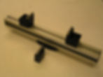

Pneumatic Vice grips
TTS 104 Relay Control
With the In-PC range of PID controllers there was a need to include control for other operations from a software front end.
This might allow a pump to be started or temperature control etc. So TTS devised a simple logic and relay control board which allows switching of these types of devices.
Used for switching HSM or HPS
Be-spoke Embedded Electronics, Software Design and Integration
Our philosophy is to provide a complete embedded electronic and software engineered package to complement existing or new mechanical installations.
This means we will:
-
Liaise with customers to fully understand the concept
-
Provide up front concept designs
-
System Prototyping and initial testing
-
System Manufacturing or manufacturing assistance
We can provide expertise in both the mechanical and electrical properties such as:
-
Embedded hardware and software using a variety of microprocessors and microcontrollers
-
User Interface – Displays, Switches, Controls
-
Unit housing – SLA mock-ups, IP ratings, EMC, Installation properties
-
Component Specification, ratings , quality, endurance
-
PCB design and manufacture along with testing
-
Engineering of actuators, sensors and mechanical component integration


Our own products were all designed by our in-house electronics engineers, if you have a need for be-spoke electronic engineering or system design then TTS can help
Our experienced engineers are happy to visit your company, assess your requirements and sit down with your engineers and develop a specification for the system you require. We would then be happy to provide you with a quotation for all stages of the project to make your system a reality.
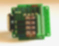
TTS SGB-033 Wheatstone Bridge completion Boards
The TTS SGB-033 bridge completion module was designed and manufactured after a large data collection exercise was requested from one of our customers.
The cost of close coupled off the shelf modules made the multiple rosette channels prohibitively expensive and so we designed the SGB-033.
The design had to include completion for both quarter and half bridge (in bending or tension/compression), sense, and of course three wire connection to the gauge .
The board is small enough to be mounted in the cable itself or next to the gauge tabs. It can be populated with a variety of resistors depending on gauge resistance and required accuracy or can be left blank for the customer to add their own resistor network.
The low price of our modules make it the cost effective way of bridge completion. Starting from just £4.00 each.

Bridge completion boards for strain gauging

Bridge completion boards 120 ohm 350 ohm for strain gauges